I have basically no experience with `circuitikz`, so we will have to wait for Rmano's input. As for the other parts,
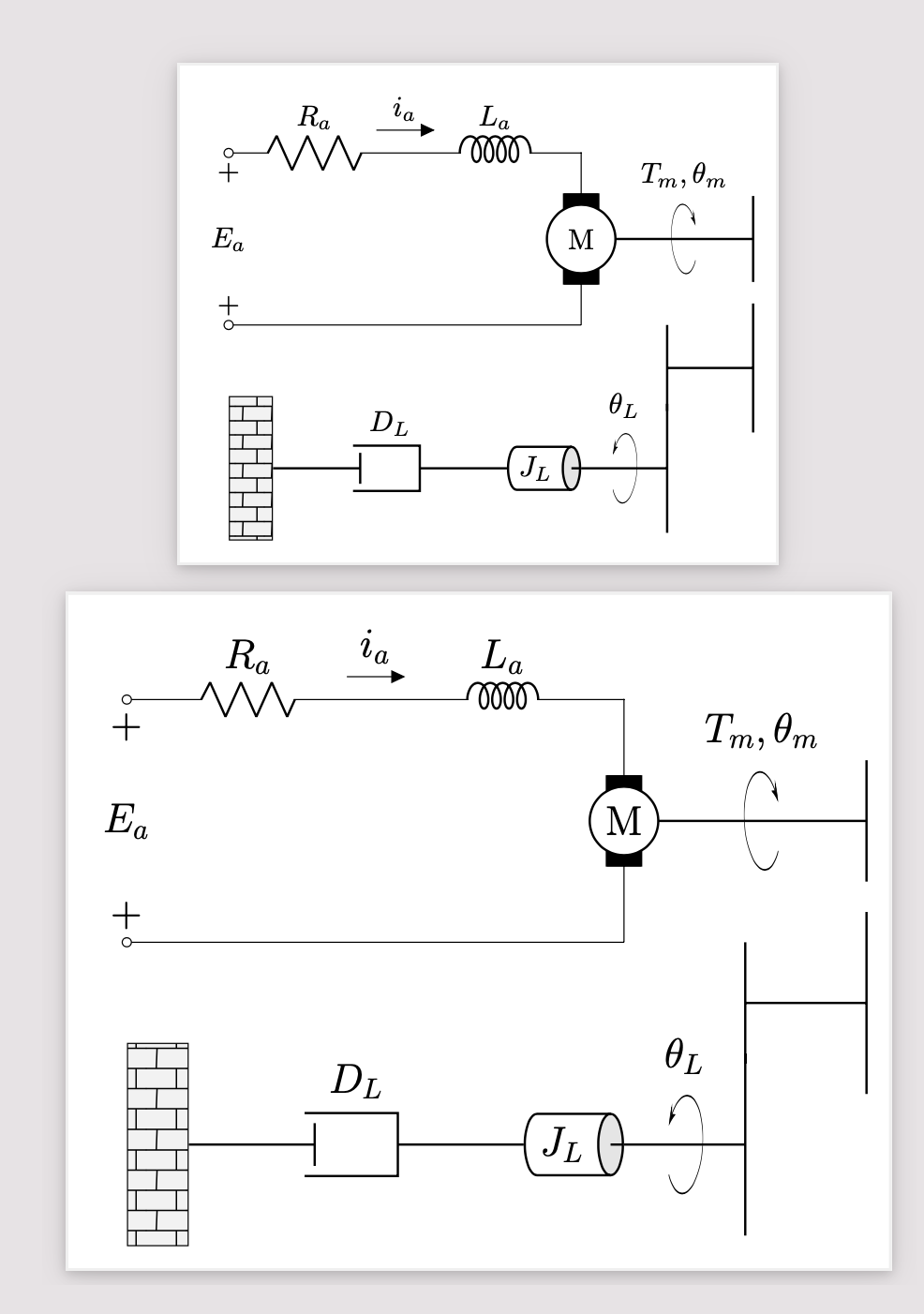
1. By setting `x=3em,y=3em`, say, you can achieve that things scale with the font size. To demonstrate this, I put the picture twice, and the second time after `\Large`. (Notice that some things do not change, such as the size of bricks and line widhts. You *can* change them if you want but generally this is not something that one does.) Presumably one can scale everything by invoking something like `scale=2.5em/1cm,transform shape`, but this might have downsides so I didn't try.
2. You were alreaady pretty good with relative positioning, the only real change is that I placed the wall first such that it aligns with the circuit, and then drew the damper (which I also modified to use `em` instead of `pt` and to accept an argument that can be used to place the label).
3. You have a couple of vertical bars, which are now `pic`s as well.
4. There are things like `Telmech` which I kept my claws away from, this is more for squirrels. :chipmunk: :smile_cat:
```
\documentclass[tikz,border=3mm]{standalone}
\usepackage[american, siunitx , RPvoltages]{circuitikz}
\usetikzlibrary{3d,arrows.meta,bending,calc,decorations.markings,patterns,positioning,shapes.geometric}
\tikzset{pics/rotarrow/.style={code={\path (160:0.4) coordinate (tmpex);
\begin{scope}[local bounding box=tmp,x={(tmpex)},
canvas is xy plane at z=0]
\clip (-0.41,-0.41) rectangle (0.41,0.41);
\pgflowlevelsynccm
\draw[thin,-{Stealth[bend]}] (-150:0.4) arc[start angle=-150,end
angle=150,radius=0.4];
\end{scope}
\path (tmp.north) node [above] {\tikzpictext};
}},pics/bar/.style={code={\draw[pic actions] (0,-#1) -- (0,#1);}},
pics/bar/.default=0.5}
\begin{document}
\begin{tikzpicture}[x=3em,y=3em, %<- this scales with the font size
damper/.style={thick,
decorate,
decoration={markings,
mark connection node=dmp,
mark=at position 0.5 with
{
\node (dmp) [thick, inner sep=0pt,
transform shape,
minimum width=2em,
minimum height=1.5em, draw=none,
#1] {};
\draw [thick] ([xshift=0.25em]dmp.north east) --
(dmp.north west) -- (dmp.south west) --
([xshift=0.25em]dmp.south east)
([yshift=-0.25em]dmp.north east) --
([yshift=0.25em]dmp.south east);
}}},]
\draw (0,2) coordinate[label=below:{$+$}] (TL)to[R=$R_a$,o-] ++(2,0)
to[short,f=$i_a$] ++(0.1,0)
to[L,cute inductor, l=$L_a$,-.] ++(2,0)
to[Telmech=M, name=M1] ++(0,-2)
to[short,-o] (0,0) coordinate[label=above:{$+$}] (ML);
\path (TL) -- node[midway]{$E_a$} (ML);
%
\path (M1) ++ (2,0) coordinate (N1);
\draw[thick] (M1) -- pic[pic text={$T_m,\theta_m$}]{rotarrow} (N1) pic[thick]{bar};
%
\draw[thick] ([yshift=-4.5em]N1) coordinate (N2) pic[thick]{bar=0.75}
-- ++ (-1,0) coordinate (N3) pic[thick]{bar};
%
\draw[thick] ([yshift=-3.5em]N3) pic[thick]{bar=0.75}
-- pic[xscale=-1, pic text={$\theta_L$}, pos=0.5 ]{rotarrow}
++ (-1,0) node[anchor=top,cylinder, black, shape border rotate=0, draw,
minimum height=2, minimum width=1, aspect=0.4,
cylinder uses custom fill, cylinder end fill = gray!20,
path picture={\draw($(c.before top)!0.5!(c.after top)$) -- (c.top);}]
(c) {$J_L$};
%
\path (TL|-c) node[draw, rectangle, minimum height=5em, minimum width = 1.5em,
anchor=west,preaction = {fill=gray!10},pattern=bricks](bricks) {};
%
\draw [damper={label=below:{$D_L$}}] (c.west) -- (bricks);
%
\end{tikzpicture}
\Large
\begin{tikzpicture}[x=3em,y=3em, %<- this scales with the font size
damper/.style={thick,
decorate,
decoration={markings,
mark connection node=dmp,
mark=at position 0.5 with
{
\node (dmp) [thick, inner sep=0pt,
transform shape,
minimum width=2em,
minimum height=1.5em, draw=none,
#1] {};
\draw [thick] ([xshift=0.25em]dmp.north east) --
(dmp.north west) -- (dmp.south west) --
([xshift=0.25em]dmp.south east)
([yshift=-0.25em]dmp.north east) --
([yshift=0.25em]dmp.south east);
}}},]
\draw (0,2) coordinate[label=below:{$+$}] (TL)to[R=$R_a$,o-] ++(2,0)
to[short,f=$i_a$] ++(0.1,0)
to[L,cute inductor, l=$L_a$,-.] ++(2,0)
to[Telmech=M, name=M1] ++(0,-2)
to[short,-o] (0,0) coordinate[label=above:{$+$}] (ML);
\path (TL) -- node[midway]{$E_a$} (ML);
%
\path (M1) ++ (2,0) coordinate (N1);
\draw[thick] (M1) -- pic[pic text={$T_m,\theta_m$}]{rotarrow} (N1) pic[thick]{bar};
%
\draw[thick] ([yshift=-4.5em]N1) coordinate (N2) pic[thick]{bar=0.75}
-- ++ (-1,0) coordinate (N3) pic[thick]{bar};
%
\draw[thick] ([yshift=-3.5em]N3) pic[thick]{bar=0.75}
-- pic[xscale=-1, pic text={$\theta_L$}, pos=0.5 ]{rotarrow}
++ (-1,0) node[anchor=top,cylinder, black, shape border rotate=0, draw,
minimum height=2, minimum width=1, aspect=0.4,
cylinder uses custom fill, cylinder end fill = gray!20,
path picture={\draw($(c.before top)!0.5!(c.after top)$) -- (c.top);}]
(c) {$J_L$};
%
\path (TL|-c) node[draw, rectangle, minimum height=5em, minimum width = 1.5em,
anchor=west,preaction = {fill=gray!10},pattern=bricks](bricks) {};
%
\draw [damper={label=below:{$D_L$}}] (c.west) -- (bricks);
%
\end{tikzpicture}
\end{document}
```
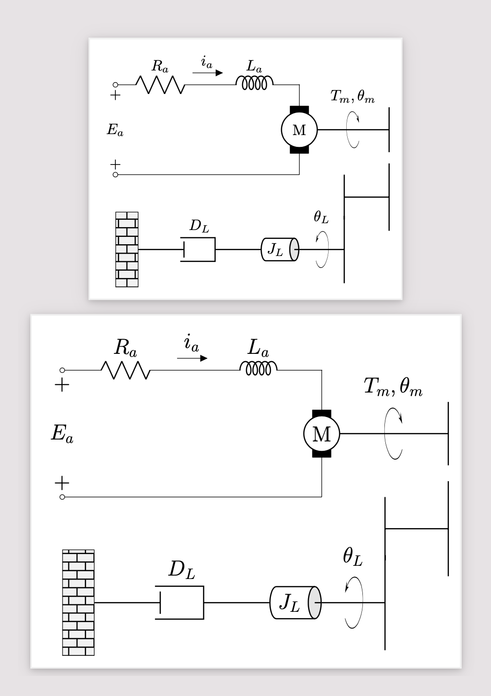
Here is an addendum on patterns. This one scales, but only after using `{Bricks[brick width=1.01em,brick height=1.01em]}` in one code and `{Bricks[brick width=1em,brick height=1em]}` in the other because otherwise Ti*k*Z wants so be efficient and thinks: I already did the one with `1em` so I can just recycle that one. The pattern offset is not fixed here (but in principle it could with more efforts, see [here](https://tex.stackexchange.com/a/545846)).
```
\documentclass[tikz,border=3mm]{standalone}
\usepackage[american, siunitx , RPvoltages]{circuitikz}
\usetikzlibrary{3d,arrows.meta,bending,calc,decorations.markings,patterns.meta,positioning,shapes.geometric}
\pgfdeclarepattern{name=Bricks,
parameters={\brickwidth,\brickheight,\brickangle,\bricklinewidth},
bottom left={\pgfpoint{-.1pt}{-.1pt}},
top right={\pgfpoint{\brickwidth+.1pt}{\brickheight+.1pt}},
tile size={\pgfpoint{\brickwidth}{\brickheight}},
tile transformation={\pgftransformrotate{\brickangle}},
code={
\pgfsetlinewidth{\bricklinewidth}
\pgfpathmoveto{\pgfpoint{-.1pt}{0pt}}
\pgfpathlineto{\pgfpoint{\brickwidth+.1pt}{0pt}}
\pgfpathmoveto{\pgfpoint{-.1pt}{0.5*\brickheight}}
\pgfpathlineto{\pgfpoint{\brickwidth+.1pt}{0.5*\brickheight}}
\pgfpathmoveto{\pgfpoint{0.25*\brickwidth}{0pt}}
\pgfpathlineto{\pgfpoint{0.27*\brickwidth}{0.5*\brickheight}}
\pgfpathmoveto{\pgfpoint{0.75*\brickwidth}{0.5*\brickheight}}
\pgfpathlineto{\pgfpoint{0.75*\brickwidth}{\brickheight}}
\pgfusepath{stroke}
} }
\tikzset{/pgf/pattern keys/.cd,
brick width/.store in=\brickwidth,
brick height/.store in=\brickheight,
brick angle/.store in=\brickangle,
brick line width/.store in=\bricklinewidth,
brick width=1em,
brick height=1em,
brick angle=0pt,
brick line width=.5pt,
}
\tikzset{pics/rotarrow/.style={code={\path (160:0.4) coordinate (tmpex);
\begin{scope}[local bounding box=tmp,x={(tmpex)},
canvas is xy plane at z=0]
\clip (-0.41,-0.41) rectangle (0.41,0.41);
\pgflowlevelsynccm
\draw[thin,-{Stealth[bend]}] (-150:0.4) arc[start angle=-150,end
angle=150,radius=0.4];
\end{scope}
\path (tmp.north) node [above,style/.expanded=\tikzpictextoptions] {\tikzpictext};
}},pics/bar/.style={code={\draw[pic actions] (0,-#1) -- (0,#1);}},
pics/bar/.default=0.5}
\begin{document}
\begin{tikzpicture}[x=3em,y=3em, %<- this scales with the font size
damper/.style={thick,
decorate,
decoration={markings,
mark connection node=dmp,
mark=at position 0.5 with
{
\node (dmp) [thick, inner sep=0pt,
transform shape,
minimum width=2em,
minimum height=1.5em, draw=none,
#1] {};
\draw [thick] ([xshift=0.25em]dmp.north east) --
(dmp.north west) -- (dmp.south west) --
([xshift=0.25em]dmp.south east)
([yshift=-0.25em]dmp.north east) --
([yshift=0.25em]dmp.south east);
}}},]
\draw (0,2) coordinate[label=below:{$+$}] (TL)to[R=$R_a$,o-] ++(2,0)
to[short,f=$i_a$] ++(0.1,0)
to[L,cute inductor, l=$L_a$,-.] ++(2,0)
to[Telmech=M, name=M1] ++(0,-2)
to[short,-o] (0,0) coordinate[label=above:{$+$}] (ML);
\path (TL) -- node[midway]{$E_a$} (ML);
%
\path (M1) ++ (2,0) coordinate (N1);
\draw[thick] (M1) -- pic[pic text={$T_m,\theta_m$}]{rotarrow} (N1) pic[thick]{bar};
%
\draw[thick] ([yshift=-4.5em]N1) coordinate (N2) pic[thick]{bar=0.75}
-- ++ (-1,0) coordinate (N3) pic[thick]{bar};
%
\draw[thick] ([yshift=-3.5em]N3) pic[thick]{bar=0.75}
-- pic[xscale=-1,pic text={$\theta_L$}, pos=0.5 ]{rotarrow}
++ (-1,0) node[anchor=top,cylinder, black, shape border rotate=0, draw,
minimum height=2, minimum width=1, aspect=0.4,
cylinder uses custom fill, cylinder end fill = gray!20,
path picture={\draw($(c.before top)!0.5!(c.after top)$) -- (c.top);}]
(c) {$J_L$};
%
\path (TL|-c) node[draw, rectangle, minimum height=5em, minimum width = 1.5em,
anchor=west,preaction = {fill=gray!10},
pattern={Bricks[brick width=1.01em,brick height=1.01em]}](bricks) {};
%
\draw [damper={label={below:{$D_L$}}}] (c.west) -- (bricks);
%
\end{tikzpicture}
\Large
\begin{tikzpicture}[x=3em,y=3em, %<- this scales with the font size
damper/.style={thick,
decorate,
decoration={markings,
mark connection node=dmp,
mark=at position 0.5 with
{
\node (dmp) [thick, inner sep=0pt,
transform shape,
minimum width=2em,
minimum height=1.5em, draw=none,
#1] {};
\draw [thick] ([xshift=0.25em]dmp.north east) --
(dmp.north west) -- (dmp.south west) --
([xshift=0.25em]dmp.south east)
([yshift=-0.25em]dmp.north east) --
([yshift=0.25em]dmp.south east);
}}},]
\draw (0,2) coordinate[label=below:{$+$}] (TL)to[R=$R_a$,o-] ++(2,0)
to[short,f=$i_a$] ++(0.1,0)
to[L,cute inductor, l=$L_a$,-.] ++(2,0)
to[Telmech=M, name=M1] ++(0,-2)
to[short,-o] (0,0) coordinate[label=above:{$+$}] (ML);
\path (TL) -- node[midway]{$E_a$} (ML);
%
\path (M1) ++ (2,0) coordinate (N1);
\draw[thick] (M1) -- pic[pic text={$T_m,\theta_m$}]{rotarrow} (N1) pic[thick]{bar};
%
\draw[thick] ([yshift=-4.5em]N1) coordinate (N2) pic[thick]{bar=0.75}
-- ++ (-1,0) coordinate (N3) pic[thick]{bar};
%
\draw[thick] ([yshift=-3.5em]N3) pic[thick]{bar=0.75}
-- pic[xscale=-1, pic text={$\theta_L$}, pos=0.5 ]{rotarrow}
++ (-1,0) node[anchor=top,cylinder, black, shape border rotate=0, draw,
minimum height=2, minimum width=1, aspect=0.4,
cylinder uses custom fill, cylinder end fill = gray!20,
path picture={\draw($(c.before top)!0.5!(c.after top)$) -- (c.top);}]
(c) {$J_L$};
%
\path (TL|-c) node[draw, rectangle, minimum height=5em, minimum width = 1.5em,
anchor=west,preaction = {fill=gray!10},
pattern={Bricks[brick width=1em,brick height=1em]}](bricks) {};
%
\draw [damper={label={below:{$D_L$}}}] (c.west) -- (bricks);
%
\end{tikzpicture}
\end{document}
```