This really feels very close to a circuit – and I'm sure `circuitikz` has a way to provide a rectangular shape with multiple inputs and outputs without having to misuse a built-in element – but in case you want a plain-ish TikZ solution, I'll add one with my tools, i.e. the ones from my [`tikz-ext` package](https://ctan.org/pkg/tikz-ext) – so much for *plain*.
Here, I'm using `ext.paths.ortho` and its `ext/horizontal vertical horizontal` key for the `-|-` path operation and `ext.arrows-plus` for adding arrow tips along path operation. Since you don't have any curved lines the `ext/arrow` pic is enough.
For a rectangle with multiple, evenly spaced inputs and output anchors, I'm using a slight alteration to the `\pgfDeclareGenericAnchorsLinear` macro from [an answer on the other site](https://tex.stackexchange.com/a/247894/16595). There's also a [similar, less automatic version available](https://tex.stackexchange.com/a/691974/16595).
Basically, with
```
define linear anchors={north west}{south west}{3}{west}{funcHalfPadding}
```
three generic anchors
* `west 1/3`,
* `west 2/3` and
* `west 3/3`
are defined that are placed according to the PGFMath function `funcHalfPadding` between a shape's `north west` and `south east` anchors.
Generic means that these are always available for every node and every shape (at least in the scope where this key/macro is used – which is the whole document in this case).
---
Both the `Triangle` arrow tip as well as the `Circle` are placed as arrow tips, the default settings makes it so that they are centered-ish along the line and not placed with their tip at the center which visually looks too offset. Technically, you don't need to use arrow tips here, you could just place a node, say `node[circle, fill]{}` for the circle, or a custom pic along a path. Unfortunately, the [manual's example](https://tikz.dev/tikz-pics) is a seagull which isn't very inspiring.
You could just draw your triangle yourself:
```
\tikzset{
triangle/.pic={
\draw[pic actions] (-5mm,-5mm) -- (5mm,0pt) -- (-5mm,5mm) -- cycle;}}
```
and wouldn't be constrained to the available arrow tips.
There can also be made an argument for the circle to be a node that is used to connect if it is a vertex in the graph sense and not just a annotation to the connection like the triangles. (This solution also draws the parts of the connections and some annotations twice or thrice which can be avoided by using the circular node as a vertex.)
---
If you find yourself, often needing to use these arrow tips on the `-|-` paths then you might want to define every
```
\tikzset{
->->-/.style={->-=very near start, ->-=very near end},
->---/.style={->-=very near start},
--->-/.style={->-=very near end},
-o--/.style={-o-=near start},
--o-/.style={-o-=near end}
}
```
for all variations of these connections.
## Code
```
\documentclass[tikz]{standalone}
\usetikzlibrary{arrows.meta, ext.arrows-plus, ext.paths.ortho, positioning, quotes}
\makeatletter % https://tex.stackexchange.com/a/247894/16595
\newcommand*\pgfDeclareGenericAnchorsLinear[5]{% #1 = anchor 1, #2 = anchor 2, #3 = max number (1 ... #3), #4 = name, #5 = function name
\pgfmathloop
\csname pgfmath#5@\endcsname{\pgfmathcounter}{#3}%
\edef\pgf@temp{\noexpand\pgfdeclaregenericanchor{#4\space \pgfmathcounter/#3}{\noexpand\pgfpointlineattime{+\pgfmathresult}{\noexpand\pgf@sh@reanchor{########1}{#1}}{\noexpand\pgf@sh@reanchor{########1}{#2}}}}%
\pgf@temp
\ifnum\pgfmathcounter<#3\relax
\repeatpgfmathloop}
\makeatother
\pgfset{
define linear anchors/.code n args=5{\pgfDeclareGenericAnchorsLinear{#1}{#2}{#3}{#4}{#5}},
declare function={funcNormalPadding(\i,\n)=\i/(\n+1); funcHalfPadding(\i,\n)=(\i-.5)/(\n);}}
\tikzset{
define linear anchors={north west}{south west}{3}{west}{funcHalfPadding},
define linear anchors={north east}{south east}{2}{east}{funcHalfPadding}}
\tikzset{
->-/.style={edge node={pic[#1]{ext/arrow=> }}},
-o-/.style={edge node={pic[#1]{ext/arrow=Circle}}}}
\begin{document}
\begin{tikzpicture}[>=Triangle, node distance=2cm]
\node (abc) {$(a, b, c)$};
\node[right=of abc, minimum width=2cm, minimum height=3cm, draw] (f) {$\mathbf{f}$};
\node[right=of f] (xy) {$(x, y)$};
\path[ext/horizontal vertical horizontal] % -|-
(abc) foreach[count=\i] \abc in {a, b, c}{
edge[
->-=very near start,
->-=very near end,
-o-=near start,
"$\abc$" very near end] (f.west \i/3)
}
foreach[count=\i] \xy in {x, y}{
(f.east \i/2) edge[
->,
->-=very near start,
-o-=near end,
"$\xy$" very near start] (xy)
}
;
\end{tikzpicture}
\end{document}
```
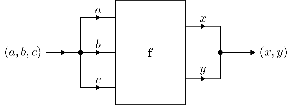
## Output