J...S

I wanted to create a block diagram like this using tikz:
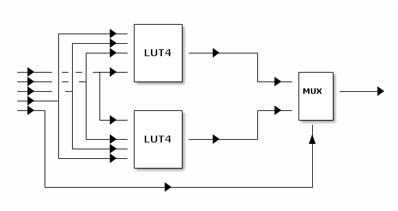
It is meant to show how two 4-input-1-output digital circuit blocks
can be combined to get a 5-input-1-output block.
I figured circuitikz would be a good way to do this.
So I tried this:
```latex
\documentclass{article}
\usepackage{circuitikz}
\usetikzlibrary{positioning}
\begin{document}
\begin{circuitikz}
\ctikzset{multipoles/thickness=3}
\ctikzset{multipoles/dipchip/width=2}
\draw (0,0)
node[dipchip,
num pins=10,
hide numbers,
no topmark,
external pins width=0
] (C) {LUT4};
\node [right, font=\tiny] at (C.bpin 1) {IN1};
\node [right, font=\tiny] at (C.bpin 2) {IN2};
\node [right, font=\tiny] at (C.bpin 4) {IN3};
\node [right, font=\tiny] at (C.bpin 5) {IN4};
\node [left, font=\tiny] at (C.bpin 8) {OUT};
\node [right of=(C.bpin 1), font=\tiny] {H};
\end{circuitikz}
\end{document}
```
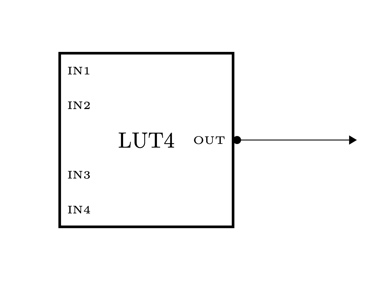
Which got part of one of the three blocks:

How can we draw wires branching off using circuitikz?
With a black dot representing branching off points.
I tried looking up the circutikz manual, but since I haven't yet spent
a lot of time on it, I couldn't get it.
Or would plain tikz be better in this case?
Can we use positions like `C.bpin 1.north`?
Top Answer
Rmano

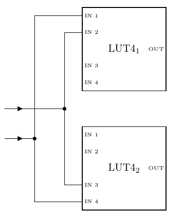
I am not sure to fully understand your question, but:
- with a recent `circuitikz`, `muxdemux` are much more configurable than chips, providing also standard labels;
- you can use a `short` with current or poles (the `i={~}` and `-*`) to add arrows or dots;
- you can simply place a `circ` node where you want it;
so for example you can have this:
```latex
\documentclass[border=10pt]{standalone}
\usepackage[T1]{fontenc}
\usepackage[siunitx, RPvoltages]{circuitikz}
\tikzset{LUT4/.style={muxdemux,
external pins width = 0,
muxdemux def={Lh=5, Rh=5, w=5,
NR=1, NL=5, NB=1, NT=1,},
muxdemux label={%
L1=IN 1, L2=IN 2, L4=IN 3, L5=IN 4,
R1=OUT},
}
}
\begin{document}
\begin{tikzpicture}[]
\path (4, 4) node[LUT4](L1){LUT4\textsubscript{1}};
\path (4, 0) node[LUT4](L2){LUT4\textsubscript{2}};
\draw (0, 1) to[short, i={~}, -*] ++(1,0) coordinate(p1);
\draw (0, 2) to[short, i={~}] ++(1,0) -- ++(1,0) node[circ]{}
coordinate(p2);
\draw (p1) |- (L1.lpin 1);
\draw (p1) |- (L2.lpin 5);
\draw (p2) |- (L1.lpin 2);
\draw (p2) |- (L2.lpin 4);
\end{tikzpicture}
\end{document}
```
You can also use the gaps (see "crossings" in the manual), but I suggest that you use the dot to mean a connection, and normal crossing otherwise (in electronic schematics that is, or should be, the standard).
Answer #2
samcarter

Inspired by the example in section "4.25.4 Chip special usage" of the user guide, you could add arrows with black dots like this:
```
\documentclass{article}
\usepackage{circuitikz}
\usetikzlibrary{positioning}
\usetikzlibrary {arrows.meta}
\begin{document}
\begin{circuitikz}
\ctikzset{multipoles/thickness=3}
\ctikzset{multipoles/dipchip/width=2}
\draw (0,0)
node[dipchip,
num pins=10,
hide numbers,
no topmark,
external pins width=0
] (C) {LUT4};
\node [right, font=\tiny] at (C.bpin 1) {IN1};
\node [right, font=\tiny] at (C.bpin 2) {IN2};
\node [right, font=\tiny] at (C.bpin 4) {IN3};
\node [right, font=\tiny] at (C.bpin 5) {IN4};
\node [left, font=\tiny] at (C.bpin 8) {OUT};
\draw[{Circle}-{Triangle}] (C.bpin 8) -- ++(2,0);
\end{circuitikz}
\end{document}
```