Here is something that should help. Basic usage is:
```
\path (0,4) [bitfield={name=top, node options={label=left:$C$}, values={1,1,1,0}}];
```
This will place a rectangular node called `top` with a “C” label on the left, as well as four square nodes called `top-1`, `top-2`, `top-3` and `top-4` containing the provided `values`. Nodes are technically not nested—this is unsupportedbut the boundary of the containing node, created using the Ti*k*Z `fit` library, is precisely aligned with the centerlines of the appropriate subnode boundaries (see below if this is unclear).
The center of the containing node is placed at the current path position, i.e. `(0,4)` in the above example.
You can use node anchors (those of `rectangle` nodes) as usual with all these and provide node options using:
- `node options={...}` for the containing node;
- `subnode options={...}` for its subnodes.
The latter Ti*k*Z style allows for automatic numbering of subnodes as in your drawing; this is because when the `subnode options` are processed:
- `\tnbNodeIndex` expands to the 1-based subnode index;
- `\tnbPrevIndex` expands to the 0-based subnode index.
Finally, the minimum side length of each subnode (all are squares) can be chosen using `cell width` as in `bitfield={..., cell width=2cm}` (the initial value of `/topnush/bitfield/cell width` is `1cm`). In any case, it must be large enough for the contents, because positioning calculations assume that it is the side length of each cell.
```
\documentclass[tikz,border=2mm]{standalone}
\usetikzlibrary{fit, shapes.geometric}
\ExplSyntaxOn
\cs_new_eq:NN \clistMapInlineNn \clist_map_inline:Nn
\cs_new_eq:NN \clistCountN \clist_count:N
\ExplSyntaxOff
\makeatletter
\newcommand{\@tnbitfield}{%
\ifx\tnb@nodename\empty
\pgfkeys{/topnush/bitfield/@set@node@name/.style={}}%
\pgfkeys{/topnush/bitfield/@set@subnode@name/.style={}}%
\else
\pgfkeys{/topnush/bitfield/@set@node@name/.style={name=\tnb@nodename}}%
\pgfkeys{
/topnush/bitfield/@set@subnode@name/.style={
name=\tnb@nodename-\tnbNodeIndex}}%
\fi
%
\edef\tnb@nbCells{\clistCountN{\tnb@values}}%
\pgfmathsetmacro{\tnb@init@x}{0.5*(1-\tnb@nbCells)}%
\pgfmathsetlengthmacro{\tnb@cell@width}
{\pgfkeysvalueof{/topnush/bitfield/cell width}}%
%
% Rembember the current position on the path so we can restore it at the end.
\tikzset{insert path={coordinate (tnb@current@pos)}}%
\def\tnbNodeIndex{0}%
%
% Loop over the provided bit values (available as ##1 below)
\clistMapInlineNn{\tnb@values}{%
\let\tnbPrevIndex\tnbNodeIndex
\edef\tnbNodeIndex{\the\numexpr \tnbNodeIndex + 1}%
% Insert a subnode into the current path
\tikzset{
insert path={
node[/topnush/bitfield/@set@subnode@name,
square, minimum size={\tnb@cell@width*sqrt(2)}, draw,
xshift={(\tnb@init@x + \tnbPrevIndex)*\tnb@cell@width},
/topnush/bitfield/subnode@opts] {##1}},
}%
}%
%
% Now insert the containing node
\tikzset{
insert path={
% These points lie on the “center line” of the border lines
++({-0.5*(\tnb@nbCells*\tnb@cell@width)}, -0.5*\tnb@cell@width)
coordinate (tnb@southWest)
++(\tnb@nbCells*\tnb@cell@width, \tnb@cell@width)
coordinate (tnb@northEast)
node[/topnush/bitfield/@set@node@name, inner sep=0pt,
fit=(tnb@southWest) (tnb@northEast), /topnush/bitfield/node@opts] {}
(tnb@current@pos) % restore the position that was current when we started
}%
}%
}
\tikzset{
square/.style={regular polygon, regular polygon sides=4},
bitfield/.code={%
\pgfqkeys{/topnush/bitfield}{#1}%
\@tnbitfield
},
/topnush/bitfield/.cd,
name/.store in=\tnb@nodename,
node options/.style={/topnush/bitfield/node@opts/.style={#1}},
subnode options/.style={/topnush/bitfield/subnode@opts/.style={#1}},
values/.store in=\tnb@values,
% Set the initial contents of the optional parameters
cell width/.initial=1cm,
name={}, % name for the containing node (empty = don't name it)
node options={},
subnode options={},
}
\makeatother
\begin{document}
\begin{tikzpicture}
\pgfmathsetlengthmacro{\myCellWidth}
{\pgfkeysvalueof{/topnush/bitfield/cell width}}%
% We have groups of 4 cells separated from each other by 1.2 cell widths
\pgfmathsetlengthmacro{\mySep}{1.2*\myCellWidth}
\pgfmathsetlengthmacro{\myDeltaWidth}{0.5*(4*\myCellWidth + \mySep)}
\path (0,4) [bitfield={name=top, node options={label=left:$C$},
values={1,1,1,0}}];
\path (-3*\myDeltaWidth,0) [bitfield={
name=A,
subnode options={label={[yshift=0.2ex]below:\tnbNodeIndex}},
values={1,0,0,1}}];
\path (-\myDeltaWidth,0) [bitfield={
name=B,
subnode options={
label={[yshift=0.2ex]below:\the\numexpr \tnbNodeIndex+4 \relax}},
values={0,0,0,1}}];
\path (\myDeltaWidth,0) [bitfield={
name=C,
subnode options={
label={[yshift=0.2ex]below:\the\numexpr \tnbNodeIndex+8 \relax}},
values={0,1,0,1}}];
\path (3*\myDeltaWidth,0) [bitfield={
name=D,
subnode options={
label={[yshift=0.2ex]below:\the\numexpr \tnbNodeIndex+12 \relax}},
values={0,0,0,0}}];
\draw (top-1.south) -- (A)
(top-2.south) -- (B)
(top-3.south) -- (C)
(top-4.south) -- (D);
\end{tikzpicture}
% Almost the same picture; simply showing a few more things you can do (node
% anchors, filling, arrows...).
\begin{tikzpicture}
\pgfmathsetlengthmacro{\myCellWidth}
{\pgfkeysvalueof{/topnush/bitfield/cell width}}%
% We have groups of 4 cells separated from each other by 1.2 cell widths
\pgfmathsetlengthmacro{\mySep}{1.2*\myCellWidth}
\pgfmathsetlengthmacro{\myDeltaWidth}{0.5*(4*\myCellWidth + \mySep)}
\path (0,4) [bitfield={
name=top, node options={fill=black!40, fill opacity=0.2, label=left:$C$},
values={1,1,1,0}}];
\path (-3*\myDeltaWidth,0) [bitfield={
name=A,
subnode options={label={[yshift=0.2ex]below:\tnbNodeIndex}},
values={1,0,0,1}}];
\path (-\myDeltaWidth,0) [bitfield={
name=B,
node options={fill=blue, fill opacity=0.2},
subnode options={
label={[yshift=0.2ex]below:\the\numexpr \tnbNodeIndex+4 \relax}},
values={0,0,0,1}}];
\path (\myDeltaWidth,0) [bitfield={
name=C,
subnode options={
label={[yshift=0.2ex]below:\the\numexpr \tnbNodeIndex+8 \relax}},
values={0,1,0,1}}];
\path (3*\myDeltaWidth,0) [bitfield={
name=D,
node options={fill=red, fill opacity=0.2},
subnode options={
label={[yshift=0.2ex]below:\the\numexpr \tnbNodeIndex+12 \relax}},
values={0,0,0,0}}];
\path (top-1.south) edge[->, shorten >=2pt] (A)
(top-2.south) edge[->] (B)
(top-3.south) edge[->] (C)
(top-4.south) edge[->, shorten >=2pt] (D)
(top.south) edge[->, orange, out=-90, in=180] (C.west)
(top.south) edge[->, teal, out=-90, in=0] (B.east);
\end{tikzpicture}
\end{document}
```
Note: the above examples all use four cells per containing node because it is this way in your prototype, however my code makes no assumption about that. For instance, using `values={0,1,0,1,0,1}` in the `bitfield` argument would yield a node containing six cells.
# About the boundary of the containing node
The boundary of the containing node is computed so that it is the same as if the outer rectangle were obtained using the `draw` option on the containing node. I did it this way so as to ensure that (line, arrow...) connections between the containing node and other nodes in the picture look the same as if the containing rectangle were drawn as a node with `rectangle` shape (in my code, the outer rectangle is not drawn *per se;* what we perceive as the outer rectangle all comes from parts of the individual cells—these are all drawn).
The following zoomed-in excerpt of the top-left part of the above picture shows the boundary of the containing node in light red, aka pink. It was obtained by inserting `draw=red!30, line width=0.1pt,` before `fit=(tnb@southWest) (tnb@northEast)`:
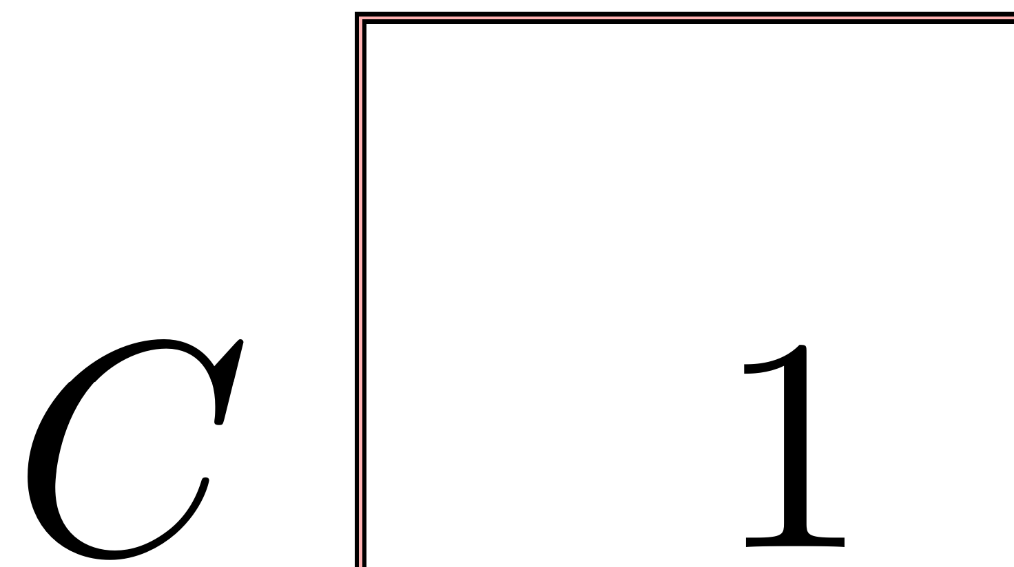
**Rationale.** In a previous version of my code, I used `fit=...` where `...` contained the list of all subnodes of the containing node being prepared; this had the effect that the pink line was stuck to the outer border(\*) of the black lines shown here. As a result, the containing node didn't connect so well with other nodes.
(\*) Please suggest better wording...