Anonymous 1123

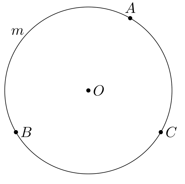
I am trying to node `m` is midpoint of the arc `AB`. I tried it by hand
```
\documentclass[tikz,border=3mm]{standalone}
\usepackage{calc}
\begin{document}
\begin{tikzpicture}[declare function={R=2;},c/.style={circle,fill,inner sep=1pt}]
\path
(0,0) coordinate (O)
({R*cos(60)},{R*sin(60)}) coordinate (A)
({R*cos(-30)},{R*sin(-30)}) coordinate (C)
({R*cos(210)},{R*sin(210)}) coordinate (B)
({R*cos(270/2)},{R*sin(270/2)}) coordinate[label=left:{$m$}] (M);
\draw (O) circle[radius = R];
\path foreach \p/\g in {O/0,A/90,B/0,C/0}
{(\p)node[c]{}+(\g:2.5mm) node{$\p$}};
\end{tikzpicture}
\end{document}
```

How to node midpoint of an arc automatically?
Top Answer
user 3.14159

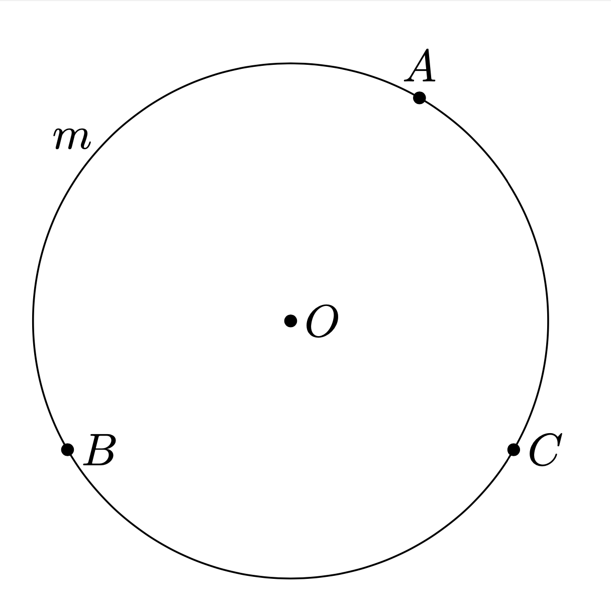
An arc between two points on a circle is not uniquely defined, there are two options. In the case at hand, there is also a midpoint close to `C` of an arc between `A` and `B` on a circle with center `O`. This is why the following code has two angles, `\n1` and `\n2`, which differ by `180`. While in this example the angles of the points are known, in general they may not be, which is why they get determined with the `calc` library. In more detail, after saying inside the `let ... in` block
```
\p{A}=(A)
```
the two lengths `\x{A}` and `\y{A}` contain the x and y coordinates on the screen. Then
```
\n{A}={scalar(atan2(\y{A},\x{A}))}
```
contains the polar angle of `A`, and likewise for `B`. Note also that using polar coordinates is convenient in this case.
```
\documentclass[tikz,border=3mm]{standalone}
\usetikzlibrary{calc}
\begin{document}
\begin{tikzpicture}[declare function={R=2;},c/.style={circle,fill,inner sep=1pt}]
\path
(0,0) coordinate (O)
(60:R) coordinate (A)
(-30:R) coordinate (C)
(210:R) coordinate (B)
let \p{A}=(A),\p{B}=(B),
\n{A}={scalar(atan2(\y{A},\x{A}))},\n{B}={scalar(atan2(\y{B},\x{B}))},
\n1={0.5*\n{A}+0.5*\n{B}},\n2={\n1+180}
in
(\n2:R) coordinate[label=left:{$m$}] (M)
;
\draw (O) circle[radius = R];
\path foreach \p/\g in {O/0,A/90,B/0,C/0}
{(\p)node[c]{}+(\g:2.5mm) node{$\p$}};
\end{tikzpicture}
\end{document}
```
