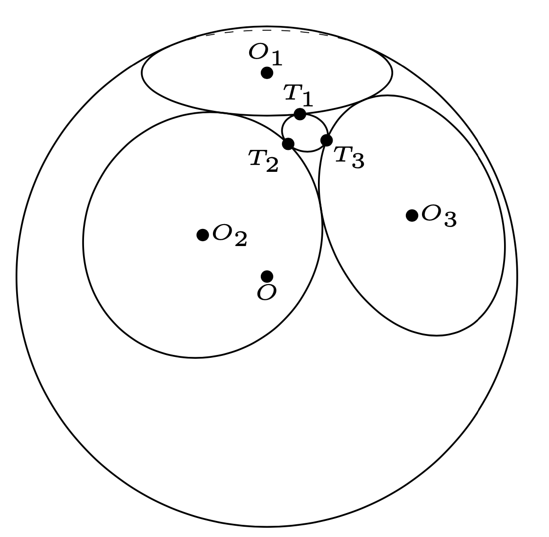
The reason why the circle is incorrect is that the code uses rounded values. On the other hand, the radius `r` of the circle is computed via
```
r=sqrt(R^2-d^2) ,
```
where `R` is the radius of the sphere and `d` is the distance of the center of the circle from the center of the sphere. If we compute the sensitivity of `r` on `d`, we need to compute the derivative of `r` w.r.t. `d` (which, among other things, also illustrates why it makes a lot of sense to distinguish differential `d`s typographically from variables `d`), we see that
```
r'=-d/sqrt(R^2-d^2) .
```
That is, if `d` is very close to `R`, then a tiny error in `d` can give you a very wrong radius.
This is confirmed with `3dtools`, with which it is rather easy to construct the circle. All we need to do is to compute two angles, `alpha` and `beta`, and to install local coordinate systems on the circles. The details are in the comments of the following code.
```
\documentclass[tikz,border=3mm]{standalone}
\usetikzlibrary{3dtools}% https://github.com/marmotghost/tikz-3dtools
\begin{document}
\begin{tikzpicture}[3d/install view={phi=110,theta=70},
line cap=butt,line join=round,c/.style={circle,fill,inner sep=1pt},
declare function={rs=2;rc=1;d=sqrt(rs*rs-rc*rc);a=sqrt(2);
% alpha is just the latitude angle of O_2 and O_3
alpha=asin(rc/rs);
% the beta angle emerges from the requirement that O--O_2 and
% O--O_3 enclose an angle of 2*alpha
beta=acos((cos(2*alpha)-pow(sin(alpha),2))/(pow(cos(alpha),2)));}]
\path
(0,0,0) coordinate (O)
(0,0,d) coordinate (O_1)
({d*cos(alpha)},0,{d*sin(alpha)}) coordinate (O_2)
({d*cos(alpha)*cos(beta)},{d*cos(alpha)*sin(beta)},{d*sin(alpha)}) coordinate (O_3);
% basis vectors for circle 2
\pgfmathsetmacro{\myexb}{TDunit("(0,0,1)x(O_2)")}
\pgfmathsetmacro{\myeyb}{TDunit("(O_2)x(\myexb)")}
% basis vectors for circle 3
\pgfmathsetmacro{\myexc}{TDunit("(0,0,1)x(O_3)")}
\pgfmathsetmacro{\myeyc}{TDunit("(O_3)x(\myexc)")}
\path[3d coordinate/.list={%
{(T_1)=(O_1)+[rc*cos(beta/2)]*(1,0,0)+[rc*sin(beta/2)]*(0,1,0)},
{(T_2)=(O_2)+[rc*cos(90-beta/2)]*(\myexb)+[rc*sin(90-beta/2)]*(\myeyb)},
{(T_3)=(O_3)+[rc*cos(90+beta/2)]*(\myexc)+[rc*sin(90+beta/2)]*(\myeyc)}}]
(O)pic[draw=none]{3d circle through 3 points={A={(T_1)},B={(T_2)},C={(T_3)},
center name=O_4}};
\draw[3d/screen coords] (O) circle[radius=rs];
\pgfmathsetmacro{\myM}{TD("(O_4)")}
\pgfmathsetmacro{\myr}{tddistance("(O_4)","(T_1)")}
\typeout{O_4=(\myM), r=\myr}
\path foreach \X in {1,2,3,4}
{ (O)pic{3d/circle on sphere={R=rs,C={(O)},P={(O_\X)}}}};
%
\path foreach \p/\g in {O/-90,O_1/90,O_2/0,O_3/0,T_1/90,T_2/-135,T_3/-45}{
(\p)node[c,label={[font=\tiny,label distance=0pt,inner sep=0pt]\g:{$\p$}}]{}};
\end{tikzpicture}
\end{document}
```

This code gets `O_4=(0.93881,0.66382,1.62599)`. The corresponding distances are
```
1.99623 for your input and 1.99145 for the 3dtools result,
```
and the resulting radii are
```
0.122701 for your input and 0.184757 for the 3dtools result,
```
respectively. As you can see, an error of about 0.25% at the level of the distance translates into a 50% error at the level of the radius. This is why the circle produced in the code you posted is incorrect.
`3dtools` uses `fpu` to counter such effects. There is no guarantee that this is always sufficient, but at least in this case it is. (It wouldn't be too difficult to use `xfp` instead because all the computations in the package yield dimensionless results. Replacing `fpu` by `xfp` blindly, however, will lead to major problems that manifest only in certain scenarios, which are, however, widely used.)
The above code is already general, i.e. can be used for various `rc`. (Of course, if the radius `rc` becomes too large, three circles will no longer fit on the sphere while touching each other only once, and then the code does not work any more.)
```
\documentclass[tikz,border=3mm]{standalone}
\usetikzlibrary{3dtools}% https://github.com/marmotghost/tikz-3dtools
\begin{document}
\foreach \rc in {1,1.1,...,3.4,3.3,3.2,...,1.1}
{\begin{tikzpicture}[3d/install view={phi=110,theta=70},
line cap=butt,line join=round,c/.style={circle,fill,inner sep=1pt},
declare function={rs=4;rc=\rc;d=sqrt(rs*rs-rc*rc);
% alpha is just the latitude angle of O_2 and O_3
alpha=90-2*atan2(rc,d);
% the beta angle emerges from the requirement that O--O_2 and
% O--O_3 enclose an angle of 2*atan2(rc,d)
beta=acos((cos(2*atan2(rc,d))-pow(sin(alpha),2))/(pow(cos(alpha),2)));
}]
\path
(0,0,0) coordinate (O)
(0,0,d) coordinate (O_1)
({d*cos(alpha)},0,{d*sin(alpha)}) coordinate (O_2)
({d*cos(alpha)*cos(beta)},{d*cos(alpha)*sin(beta)},{d*sin(alpha)}) coordinate (O_3)
;
% basis vectors for circle 2
\pgfmathsetmacro{\myexb}{TDunit("(0,0,1)x(O_2)")}
\pgfmathsetmacro{\myeyb}{TDunit("(O_2)x(\myexb)")}
% basis vectors for circle 3
\pgfmathsetmacro{\myexc}{TDunit("(0,0,1)x(O_3)")}
\pgfmathsetmacro{\myeyc}{TDunit("(O_3)x(\myexc)")}
\path[3d coordinate/.list={%
{(T_1)=(O_1)+[rc*cos(beta/2)]*(1,0,0)+[rc*sin(beta/2)]*(0,1,0)},
{(T_2)=(O_2)+[rc*cos(90-beta/2)]*(\myexb)+[rc*sin(90-beta/2)]*(\myeyb)},
{(T_3)=(O_3)+[rc*cos(90+beta/2)]*(\myexc)+[rc*sin(90+beta/2)]*(\myeyc)}}]
(O)pic[draw=none]{3d circle through 3 points={A={(T_1)},B={(T_2)},C={(T_3)},
center name=O_4}};
\draw[3d/screen coords] (O) circle[radius=rs];
\path foreach \X in {1,2,3,4}
{ (O)pic{3d/circle on sphere={R=rs,C={(O)},P={(O_\X)}}}};
\end{tikzpicture}}
\end{document}
```
