I use 3dtools
to draw a cube. I tried
xxxxxxxxxx
\documentclass[tikz,border=3mm]{standalone}
\usetikzlibrary{calc,3dtools}% https://github.com/marmotghost/tikz-3dtools
\begin{document}
\begin{tikzpicture}[3d/install view={phi=70,theta=70},line cap=butt,line join=round,c/.style={circle,fill,inner sep=1pt},
declare function={a=3;}]
\path
(a,-a,-a) coordinate (A)
(a,a,-a) coordinate (B)
(-a,a,-a) coordinate (C)
(-a,-a,-a) coordinate (D)
(a,-a,a) coordinate (E)
(a,a,a) coordinate (F)
(-a,a,a) coordinate (G)
(-a,-a,a) coordinate (H)
(0,0,0) coordinate (O)
;
\tikzset{3d/polyhedron/.cd,O={(O)},
back/.style={3d/polyhedron/complete dashes,fill=none},
fore/.style={3d/visible,fill=none},draw face with corners={{(B)},{(C)},{(G)},{(F)}},
draw face with corners={{(D)},{(C)},{(G)},{(H)}},
draw face with corners={{(E)},{(F)},{(G)},{(H)}},
draw face with corners={{(A)},{(B)},{(C)},{(D)}},
draw face with corners={{(A)},{(B)},{(F)},{(E)}},
draw face with corners={{(A)},{(E)},{(H)},{(D)}}
}
%\path foreach \p/\g in {A/-90,B/90,C/0,D/0,E/0,F/0,G/0,H/0}{(\p)node[c]{}+(\g:2.5mm) node{$\p$}};
\end{tikzpicture}
\end{document}
show all 28 lines
From the internet, I see this picture
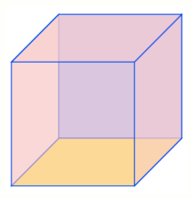
Is this an orthonormal projection of a cube? What is a nice way to draw a cube?
1 Answer
provide an answerThe projection you depict is not orthographic, and hence cannot be obtained with 3d/install view
. I recycle the proof of the first statement from here. You can still use 3dtools
to draw the cube, but this amounts to either being lucky of defining your own function for the screen depth. In this case we are lucky, but I show nevertheless how to override the screendepth
function.
xxxxxxxxxx
\documentclass[fleqn]{article}
\usepackage{amsmath}
\usepackage{marvosym}
\usepackage{tikz}
\usetikzlibrary{3dtools}% https://github.com/marmotghost/tikz-3dtools
\begin{document}
You wish to have a coordinate system that
\begin{enumerate}
\item preserves shapes and\label{preserve}
\item has $\vec e_y$ point east, $\vec e_z$ point north and $\vec e_x$ point
south west.\label{directions}
\end{enumerate}
The first requirement means that the coordinate axes are orthogonal,
\begin{equation}\label{eq:orthogonality}
\vec e_x\cdot \vec e_y=\vec e_x\cdot \vec e_z=\vec e_y\cdot \vec e_z
=0\;.
\end{equation}
So we wish to find a two--dimensional projection of these vectors that fulfill
the requirement \ref{directions}. Decompose the vectors in two--dimensional
projections on the paper plane $\vec e_i^{(\|)}$ and the orthogonal complements
$\vec e_i^{(\perp)}$. Clearly, the $\vec e_i^{(\perp)}$ are just
one--dimensional objects, which we will just call $e_i^{(\perp)}$. Requirement \ref{directions} implies that
\begin{equation}
\vec e_x^{(\|)} \cdot \vec e_y^{(\|)}=
\vec e_x^{(\|)} \cdot \vec e_z^{(\|)}=:\xi\ne0\;.
\end{equation}
Due to the orthogonality relations \eqref{eq:orthogonality}, this means that
\begin{equation}
e_x^{(\perp)} \cdot e_y^{(\perp)}=
e_x^{(\perp)} \cdot e_z^{(\perp)}=-\xi\ne0\;.
\end{equation}
None of the $e_i^{(\perp)}$ may vanish as otherwise there won't be an $x$--axis,
and
\begin{equation}
e_y^{(\perp)}=e_z^{(\perp)}=-\frac{\xi}{e_x^{(\perp)}}\;.
\end{equation}
However, requirement \ref{directions}
implies that $\vec e_y^{(\|)} \cdot \vec e_z^{(\|)}=0$, so
\begin{equation}
\vec e_y\cdot \vec e_z=\vec e_y^{(\|)} \cdot \vec e_z^{(\|)}
+e_y^{(\perp)} \cdot e_z^{(\perp)}=0+\left(\frac{\xi}{e_x^{(\perp)}}\right)^2
\ne0\;.\qquad \text{\Huge\Lightning}
\end{equation}
%\clearpage
Having seen that the desired projection is not orthonormal, one may ask whether
it is possible to use \texttt{3dtools} for such projections. The answer is that
this is in principle possible. You can define your own \texttt{screendepth}
function, in this very case this is not even necessary. However, in general it
won't be easy to guess an appropriate fuction.
\begin{figure}[htb]
\centering
\begin{tikzpicture}
\pgfmathdeclarefunction*{screendepth}{3}{\pgfmathparse{0.2*#1+0.2*#2+#3}}
\path foreach \Xa/\Ya in {-1/A,1/B}
{foreach \Xb/\Yb in {-1/A,1/B}
{foreach \Xc/\Yc in {-1/A,1/B}
{(\Xa,\Xb,\Xc) coordinate (\Ya\Yb\Yc)}}} ;
\tikzset{3d/polyhedron/.cd,
fore/.append style={fill opacity=0.5},
edges have complete dashes,
draw face with corners={{(AAA)},{(AAB)},{(ABB)},{(ABA)}},
draw face with corners={{(AAA)},{(AAB)},{(BAB)},{(BAA)}},
draw face with corners={{(AAA)},{(BAA)},{(BBA)},{(ABA)}},
draw face with corners={{(BAA)},{(BAB)},{(BBB)},{(BBA)}},
draw face with corners={{(ABA)},{(ABB)},{(BBB)},{(BBA)}},
draw face with corners={{(AAB)},{(BAB)},{(BBB)},{(ABB)}}}
\end{tikzpicture}
\end{figure}
\end{document}
show all 70 lines
However, when using this projection, then it is no longer clear how to rotate the cube, etc. This projection can still be useful for sketches.