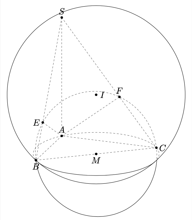
A full solution is not easy, at least I do not see an easy solution. In this case you can just measure the screen depth of `C` vs. `I` to decide which parts of the circle should be "visible". (In principle this would have to be done for `B`, too, but this one happens to sit at the projection of the sphere on the screen.)
```
\documentclass[tikz,border=3mm]{standalone}
\usetikzlibrary{calc,3dtools}
\begin{document}
\begin{tikzpicture}[line cap=round,line join=round,
3d/install view={phi=110,theta=70},
declare function={a=3;b=4;h=5;},c/.style={circle,fill,inner sep=1pt}]
\path
(0,0,0) coordinate (A)
(a,0,0) coordinate (B)
(0,b,0) coordinate (C)
(0,0,h) coordinate (S)
%(a/2,b/2,0) coordinate (M)
;
\path[3d/circumsphere center={A={(A)},B={(B)},C={(C)},D={(S)}}]
coordinate (I);
\pgfmathsetmacro{\myR}{sqrt(TD("(I)-(A)o(I)-(A)"))} ;
\draw[3d/screen coords] (I) circle[radius=\myR];
\path[3d/circumcircle center={A={(A)},B={(B)},C={(C)}}] coordinate (O);
\path pic{3d/circle on sphere={R=\myR,C={(I)}, P={(O)}}};
\path[3d/line through={(S) and (B) named lSB}];
\path[3d/line through={(S) and (C) named lSC}];
\path[3d/project={(A) on lSB}] coordinate (E);
\path[3d/project={(A) on lSC}] coordinate (F);
%\path[3d/circumcircle center={A={(E)},B={(B)},C={(C)}}] coordinate (M);
\path pic[draw=none]{3d circle through 3 points={%
A={(B)},B={(E)},C={(F)},center name=M}};
\pgfmathsetmacro{\myr}{tddistance("(B)","(M)")}%
\pgfmathsetmacro{\myIC}{TD("(C)-(I)")}
\pgfmathtruncatemacro{\itest}{screendepth(\myIC)<0?0:1}
\ifnum\itest=0
\begin{scope}
\clip[3d/screen coords] (I) circle[radius=\myR];
\path pic[3d/hidden]{3d circle through 3 points={%
A={(B)},B={(E)},C={(F)},center name=M}};
\end{scope}
\begin{scope}
\clip[3d/screen coords,even odd clip] (I) circle[radius=\myR]
[generous outside path];
\path pic[3d/visible]{3d circle through 3 points={%
A={(B)},B={(E)},C={(F)},center name=M}};
\end{scope}
\else
\tikzset{3d/define orthonormal dreibein={A={(B)},B={(C)},C={(F)}}}
\begin{scope}[x={(ex)},y={(ey)},z={(ez)},shift={(M)}]
\draw[3d/hidden] (B) arc[start angle=180,end angle=0,radius=\myr];
\draw[3d/visible] (B) arc[start angle=180,end angle=360,radius=\myr];
\end{scope}
\fi
\path foreach \p/\g in {A/90,B/-90,C/0,S/90,E/180,F/90,I/0,M/-90}
{(\p)node[c]{}+(\g:2.5mm) node{$\p$}};
\draw[3d/hidden] (S) -- (A) (S) --(B) (S) -- (C) (A) -- (B) -- (C) -- cycle (A) -- (E) (A) -- (F);
\end{tikzpicture}
\end{document}
```
