You already have answers using a patch plot and using a loop over a table. Here is a third option using a `scatter plot`. Note that many plot types are secretly scatter plots. In fact, this code is an adaptation of some answer on TeX.SE which served a slightly different purpose. Let me first mention a downside of the current implementation: you need to set `xmax` and `ymax` by hand. This can be avoided by letting LaTeX find these values, but since you generate the data automatically you may also let your code this. In case this is needed, I will be happy to add this to the answer.
Next, let us disect the code. With `clip mode=individual,` we turn on individual clipping, you can turn this off in the current version or for testing. More importantly, with
```
visualization depends on={value \thisrow{xmin} \as \myxmin},
visualization depends on={value \thisrow{xmax} \as \myxmax},
visualization depends on={value \thisrow{ymin} \as \myymin},
visualization depends on={value \thisrow{ymax} \as \myymax},
visualization depends on={value \thisrow{color} \as \mycolor},
visualization depends on={value \thisrow{label} \as \mylabel},
```
we make the entries of the current row available to the scatter code. The scatter code is
```
scatter/@pre marker code/.append code={
\pgfkeys{/pgf/fpu=true,/pgf/fpu/output format=fixed}
\path[draw=black,fill=\mycolor]
(axis direction cs:0,0) rectangle
(axis direction cs:\myxmax-\myxmin,\myymax-\myymin);
\path (axis direction cs:0.5*\myxmax-0.5*\myxmin,0)
node[above]{\mylabel};
\pgfplotsset{mark=none}
```
It contains Ti*k*Z directives that make use of the macros that we got out of the table entries.
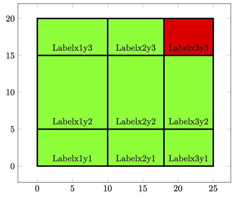
And here are the current version of the complete code and the result.
```
\begin{filecontents}[overwrite]{patches.txt}
xmin ymin xmax ymax color label
% First Column
0 0 10 5 green Labelx1y1
0 5 10 15 green Labelx1y2
0 15 10 20 green Labelx1y3
% Second Column
10 0 18 5 green Labelx2y1
10 5 18 15 green Labelx2y2
10 15 18 20 green Labelx2y3
% Third Column
18 0 25 5 green Labelx3y1
18 5 25 15 green Labelx3y2
18 15 25 20 red Labelx3y3
\end{filecontents}
\documentclass[tikz,border=3mm]{standalone}
\usepackage{pgfplots}
\pgfplotsset{compat=1.17}
\begin{document}
\begin{tikzpicture}
\begin{axis}[width=10cm,xmax=27.5,ymax=22.5]
\addplot[scatter,only marks,
clip mode=individual,
visualization depends on={value \thisrow{xmin} \as \myxmin},
visualization depends on={value \thisrow{xmax} \as \myxmax},
visualization depends on={value \thisrow{ymin} \as \myymin},
visualization depends on={value \thisrow{ymax} \as \myymax},
visualization depends on={value \thisrow{color} \as \mycolor},
visualization depends on={value \thisrow{label} \as \mylabel},
scatter/@pre marker code/.append code={
\pgfkeys{/pgf/fpu=true,/pgf/fpu/output format=fixed}
\path[draw=black,fill=\mycolor]
(axis direction cs:0,0) rectangle
(axis direction cs:\myxmax-\myxmin,\myymax-\myymin);
\path (axis direction cs:0.5*\myxmax-0.5*\myxmin,0)
node[above]{\mylabel};
\pgfplotsset{mark=none}
},
] table {patches.txt};
\end{axis}
\end{tikzpicture}
\end{document}
```
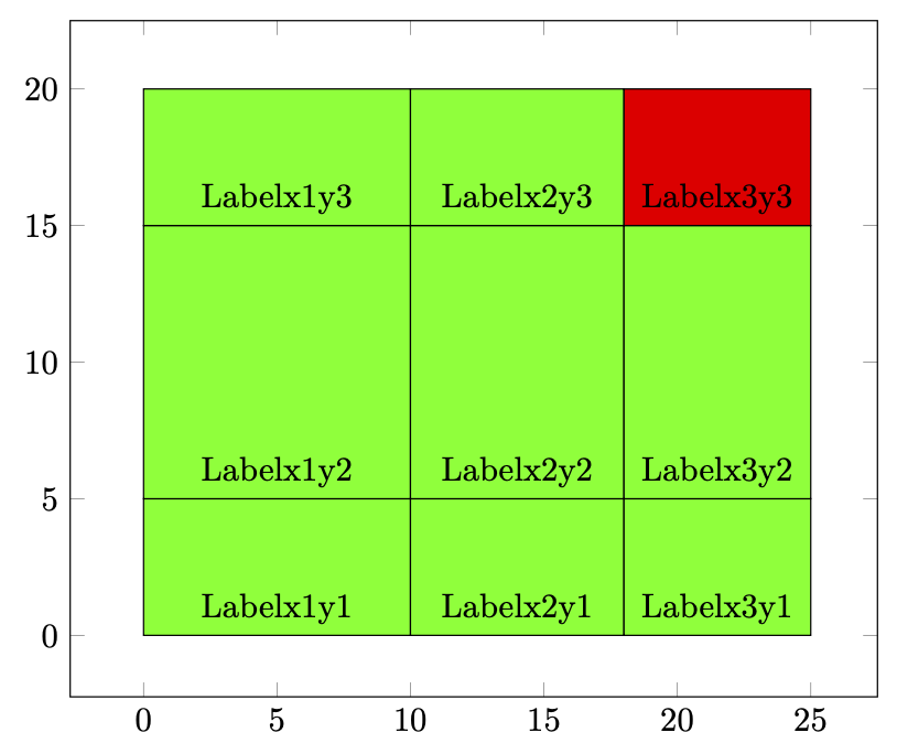
And here is a code that gets `xmax` and `ymax` from the table.
```
\begin{filecontents}[overwrite]{patches.txt}
xmin ymin xmax ymax color label
% First Column
0 0 10 5 green Labelx1y1
0 5 10 15 green Labelx1y2
0 15 10 20 green Labelx1y3
% Second Column
10 0 18 5 green Labelx2y1
10 5 18 15 green Labelx2y2
10 15 18 20 green Labelx2y3
% Third Column
18 0 25 5 green Labelx3y1
18 5 25 15 green Labelx3y2
18 15 25 20 red Labelx3y3
\end{filecontents}
\documentclass[tikz,border=3mm]{standalone}
\usepackage{pgfplots}
\pgfplotsset{compat=1.17}
\begin{document}
\begin{tikzpicture}
\pgfplotstableread{patches.txt}\dataA
\pgfmathsetmacro{\currentxmax}{-16000}%
\pgfplotstableforeachcolumnelement{xmax}\of\dataA\as\myx{%
\pgfmathsetmacro{\currentxmax}{max(\currentxmax,\myx)}}
\pgfmathsetmacro{\currentymax}{-16000}%
\pgfplotstableforeachcolumnelement{ymax}\of\dataA\as\myy{%
\pgfmathsetmacro{\currentymax}{max(\currentymax,\myy)}}
\begin{axis}[width=10cm,xmax=1.1*\currentxmax,ymax=1.1*\currentymax]
\addplot[scatter,only marks,
clip mode=individual,
visualization depends on={value \thisrow{xmin} \as \myxmin},
visualization depends on={value \thisrow{xmax} \as \myxmax},
visualization depends on={value \thisrow{ymin} \as \myymin},
visualization depends on={value \thisrow{ymax} \as \myymax},
visualization depends on={value \thisrow{color} \as \mycolor},
visualization depends on={value \thisrow{label} \as \mylabel},
scatter/@pre marker code/.append code={
\pgfkeys{/pgf/fpu=true,/pgf/fpu/output format=fixed}
%\pgfmathsetmacro\negheight{-1*\myx}
\path[draw=black,ultra thick,fill=\mycolor]
(axis direction cs:0,0) rectangle
(axis direction cs:\myxmax-\myxmin,\myymax-\myymin);
%\path (axis cs:\myxmax,\myymax);
\path (axis direction cs:0.5*\myxmax-0.5*\myxmin,0)
node[above]{\mylabel};
\pgfplotsset{mark=none}
},
] table {patches.txt};
\end{axis}
\end{tikzpicture}
\end{document}
```